As you begin diving into hardware hacking and reading printed circuit boards (PCB) you will likely come across several common protocols. This article isn’t intended to be an exhaustive list of content, but rather a quick guide to identifying which protocols are commonly used, what they require, and what common tools will let you interface with them. I’ll be covering the following protocols in this article:
- RS-232
- USB
- I2C
- SPI
- JTAG
- UART
- USART
Recommended Standard 232 (RS-232)
RS-232 is generally used to refer to any serial communication. It has (mostly) been supplanted by USB, which although it has shorter transmission distances, features lower power consumption and higher transmission rates. It is still sometimes used for access to servers, network equipment, etc. You can easily find USB-to-Serial cables. RS-232 uses signal levels relative to a common ground, so a positive voltage (+3V through +15V) indicates a “0” value, and a negative voltage (-3V through -15V) indicates a “1” value.
Universal Serial Bus (USB)
It is assumed that the various USB connectors (most commonly, Type A, Type B, Mini A, Mini B, Micro B, Micro AB, and Type C) are well known. All USB variants from 1.0 through 3.0 deliver 5V / 3A service, with the exception of power delivery specs which are typically 20V / 5 A. Upon connection devices are identified by the host sending a reset signal to the connected device, then reading the device ID and information. The standard pins are:
- Pin 1: +5V DC (VBUS)
- Pin 2: Data- (D-)
- Pin 3: Data+ (D+)
- Pin 4: Ground (GND)
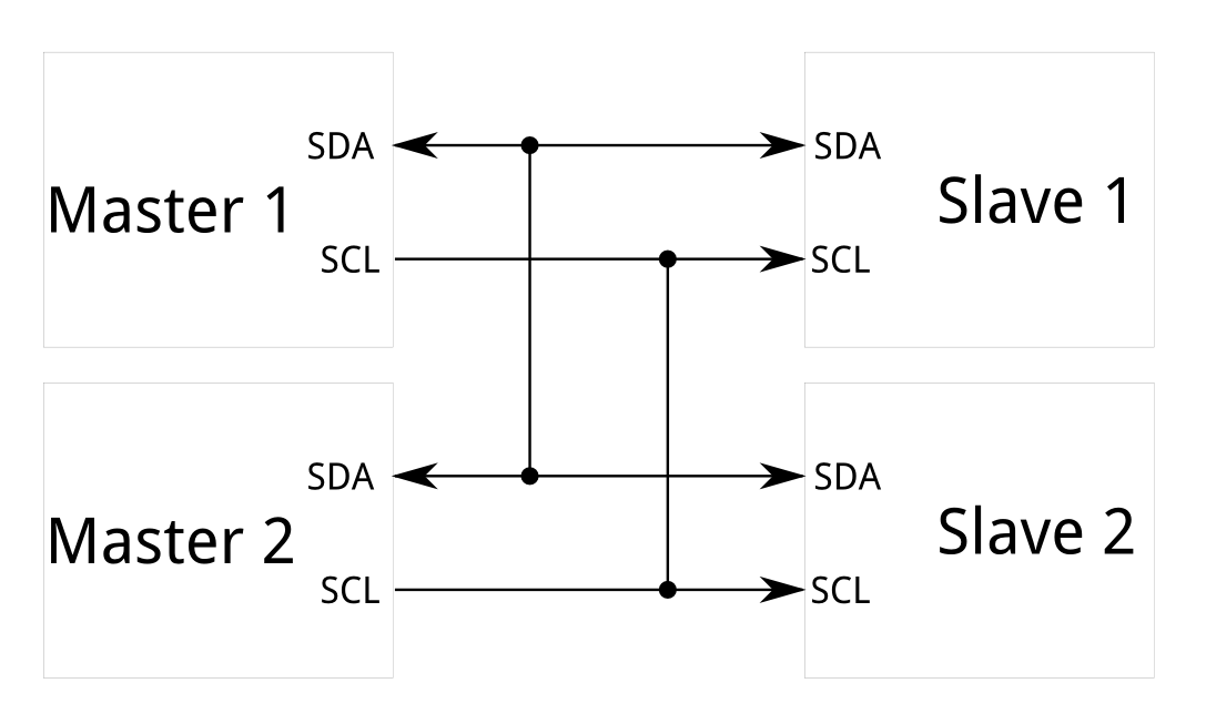
Inter-Integrated Circuit (I2C)
I2C is often used for low-speed communications between chips. It allows for addressing multiple devices (7 bits are used for this, leading to up to 128 addressable devices), and only requires two pins, so it has low overhead. The two pins are:
- Pin 1: Serial Data Line (SDA)
- Pin 2: Serial Clock Line (SCL)
Either + 3.3V or +5 V voltages may be used. The system has two “roles” that may be used: master nodes and slave nodes. There may be multiple of each. Master nodes both provide clock signals and request communications. Slave nodes only receive clock signals and respond when requested. The Bus Pirate (available here) can be used to directly communicate via I2C.
Serial Peripheral Interface (SPI)
SPI is similar to I2C in that it uses a master/slave relationship, but only allows for a single master to be present. Unlike I2C which alternates between communications requests and responses, SPI is full duplex. SPI requires four pins, which are:
- Pin 1: Serial Clock (SCLK)
- Pin 2: Master Output Slave Input (MOSI)
- Pin 3: Master Input Slave Output (MISO)
- Pin 4: Slave Select
The master node communicates to slaves via the MOSI pin and the slaves respond back via the MISO pin. The Bus Pirate (available here) can be used to directly communicate via SPI.
Joint Test Action Group (JTAG)
A standard way to test PCBs and designs, which uses a standard debug port and serial communications to communicate with a test access port (TAP) on the connected chips. This may be used to gain access to restricted system functions, to reprogram integrated circuits/storage chips/flash memory, built in tests, etc. There are five standard pins:
- Pin 1: Test Data In (TDI)
- Pin 2: Test Data Out (TDO)
- Pin 3: Test Clock (TCK)
- Pin 4: Test Mode Select (TMS)
- Pin 5: Test Reset (TRST)
However, only the first four pins are strictly required, as TRST is optional. There is a two pin variant similar to I2C as well (compact JTAG, or cJTAG) which only uses a serial data pin (TMSC / Test Serial Data) and a clock pin (TCKC / Test Clock). There are also several other implementations (see Identifying JTAG for examples).
Identifying which pins are used for what purposes on a chip may not always be easy. A JTAGulator device can automatically map this, and devices such as the Shikra (available here) or Bus Pirate (available here) can be used to directly communicate.
Universal Asynchronous Receiver Transmitter (UART)
Unlike SPI and I2C, UART isn’t a communications protocol. It is used to send data back and forth between chips and/or integrated circuits. It also only requires two pins:
- Pin 1: Transmit (TX)
- Pin 2: Receive (RX)
UART does not include any configuration information, so both sides must be set to use the same types of communication (serial vs. parallel, baud rate, transmission type, etc).
Universal Synchronous and Asynchronous Receiver Transmitter (USART)
Think of USART as UART with master and slave designations. With this comes a third pin, which is used to specify the clock:
- Pin 1: Transmit (TX)
- Pin 2: Receive (RX)
- Pin 3: Clock (CLK)
Here’s to hoping this helps a few more people than me. Good hunting!