
There’s a designer named Bradán Lane who makes some excellent hardware, and one of my favorite things he’s created is a set of challenge coin circuits. I won’t go into too much detail on them other than to note they have a fun story line, a series of challenges, and you have to exercise some basic hardware hacking skills to participate. If you’d like more details, please check out the listing for the coin on Tindie. But what if you don’t know how to get started? Well, a friend of mine (Visual) and I recently played through this, and thought we’d document how to get started for anyone who needs a little extra help. Let’s get started!
The challenge coin communicates over UART using 9600 8N1, but there are a couple of caveats. The first, and the one that made us think we’d severely messed something up, was that it doesn’t talk to FT232 chipsets… which it turns out was pretty much every chipset that I had. 😦
This was actually called out on the previously mentioned Tindie link, but in my excitement to play I hadn’t read all the way down, where this is noted:
“IMPORTANT: The UART works with FTDI’s using the CP210x chip. It does not work with several FTDI’s using the FT232 chip. The reason defies logic. (FTDI not included.)“
Yeah, the “IMPORTANT” part should have been a big clue. If you don’t follow this at all, don’t worry. Let’s break that down.
The first thing is that the coin uses UART, or “Universal Asynchronous Receiver Transmitter.” You can read more about that from my prior post on getting started with hardware protocols, but the short version is that you only need two pins. One is used to transmit data (TX), and one is used to receive data (RX).
There are several chipsets available that can be used to communicate with hardware devices, and they are often referred to as “FTDI” devices for the company that makes many of the chipsets (Future Technology Devices International), much in the same way that people often refer to facial tissues as Kleenex (even when not made by Kleenex). In particular, the FT232 chipset series is very popular and common… it’s used in most of the standard USB/FTDI cables you’ll find, by the Adafruit FTDI Friend, etc. And in this case, it’s completely not a viable solution. :). As Bradan has indicated, you have to use a CP210X chip for magical reasons. I’ll note here that I’m going to link to several things on Amazon in case you need them, but I want to stress that — as per my usual approach — they are raw links without any referral or other codes, and I get nothing from any clicks/use of them. 🙂
I ended up ordering this HiLetgo CP2012 USB to TTL UART 232 485 (etc) device. It’s $6.50, so it won’t break the bank, and it’s good to have a non FT232 chipset. If you don’t have any I’d also recommend some alligator clips (such as these) and female to male breadboard cables (such as these). All in you’re at less than $20.
So let’s get started! The basic way this works is we use a program on our computer to talk through the chipset to the device. The chipset just acts as a translator for the electrical signals. I often have people work with the “minicom” program as it’s pretty straightforward to use (note that I’ll be using Ubuntu for examples, and while your *nix may vary the program-specific things shouldn’t). If you don’t already have it installed you can do so under Ubuntu with:
user@system$ sudo apt update && sudo apt install minicomTo configure it just run:
user@system$ sudo minicom -sWe’ll need to configure two sets of things. The first is how the device will talk, and we do that from the Serial Port Setup menu. Set things up as follows from that menu:
- Serial Device: “A” (then enter /dev/ttyUSB0)
- Bps/Par/Bits: “C” (sets to 9600)
- Bps/Par/Bits” “Q” (sets to 8-N-1)
Then we have to setup how things will show up on the screen, and we do that from the “Screen and Keyboard” settings.
- History Size: “K” (then enter 5000)
- Add Linefeed: “P” (toggles between Yes/No, should be Yes)
- Add Carriage return: “T” (toggles between Yes/No, should be Yes)
- Line wrap: “R” (toggles between Yes/No, should be Yes)
Now go back to the main menu and choose “Save as dfl” which will make this your default configuration, then “Exit Minicom” to get back to the terminal.
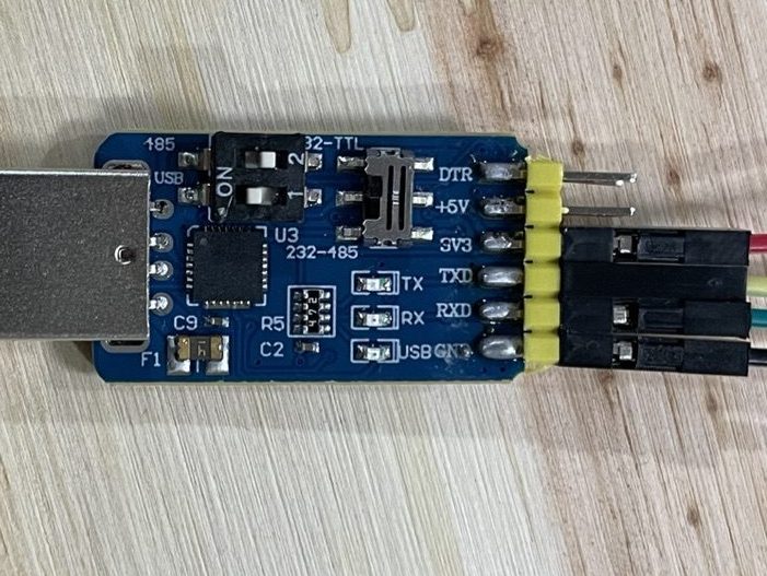
Okay, time to setup the hardware itself. If you bought that HiLetgo device mentioned previously you may have noticed there are several switches on it. The product documentation is… not great… so here’s what you need to know for that:

We’re going for USB to TTL (Transistor-to-Transistor Logic) / 232 (serial communication), so we need to set the two switches on the block to 1=On and 2=Off, then set the switch on the board directly to “On” for 232-TTL. Don’t worry too much about the why of all that, but if you prefer to just see it here’s what it should look like (it can be tough to see that switch to the right, but it’s set to the “up” position in the picture below, for “232-TTL”):
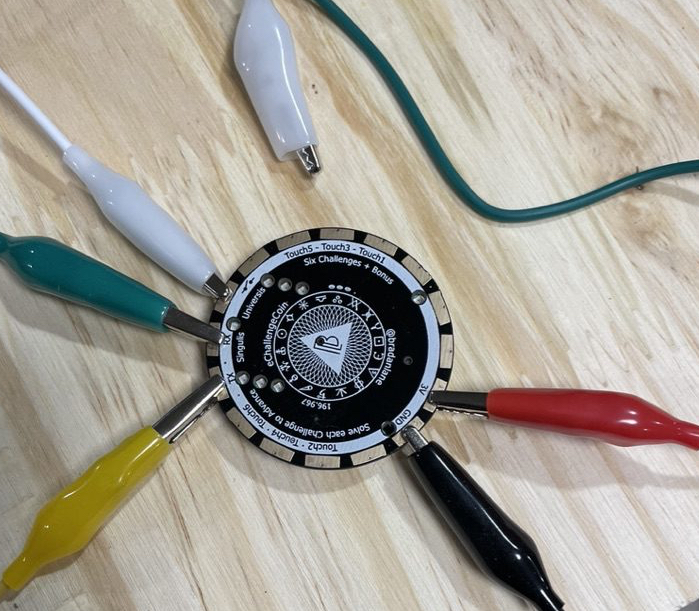
With all that set, we can cable up and connect to the challenge coin! I personally prefer to power directly from the board I’m using, then use an alligator clip to connect/disconnect power, so we used four cables. I also prefer not to have the clips stretched wide open, so I removed the back protector. If you’re going to power from the board you must remove the battery as well!

The connection of the wires is pretty straightforward. Just connect as follows:
- Board (TX) –> Coin (RX)
- The yellow cable in the image above which connects to the green alligator clip below
- Board (RX) –> Coin (TX)
- The green cable in the image above which connects to the yellow alligator clip below
- Board (GND) –> Coin (GND)
- The black cable in the image above and alligator clip below
- Board (3V3) –> Coin (3V)
- The red cable in the image above and alligator clip below
- Leave this one disconnected to start so you can power on/off the coin whenever you’d like
There is one additional clip that Visual suggested and I like, which is to clip one side of the “switch” pad set so you can just touch the alligator clip to the other side to use the wake/sleep functions (this is the white alligator clip set below). The whole thing together looks like this:
Time for the payoff! Plug your board into a USB port, then run “minicom” to start the minicom program:
user@system$ minicomThen just connect the clip for the 3V power and watch the magic start (or at least a reference to WarGames) 🙂
If it doesn’t immediately provide text output, just use the white clip/bridge the switch pads to toggle sleep mode… and press the “h” key on in minicom if you want to pull up the help menu.
Hopefully this helped, but if there’s anything that isn’t clear just let me know on Twitter and I’ll update. Good hunting!


Leave a comment