I bought a pile of DigiSpark devices on a whim (they’re less than $2 each), and the following are just my notes on how to get things up and running with them to do simple testing. I’ll also note that this was based on the DigiStump connecting tutorial, but I found some gaps in their approach and wanted to document my variations here for posterity.
Here’s the step-by-step on how to get them up and running.
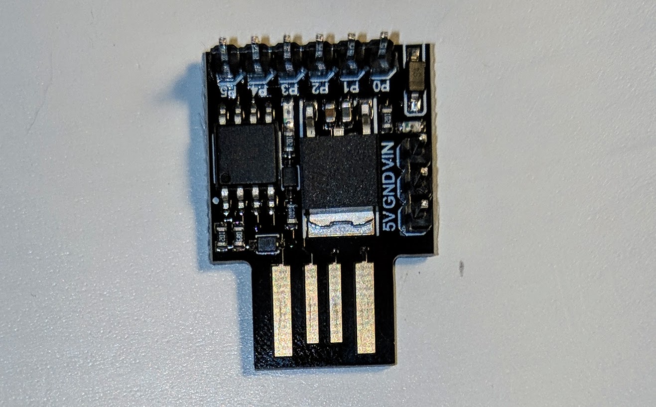
- Solder the header pins on. There should be two sets:
- Power Pins:
- VIN – Voltage Input, unregulated, should be 9-12V DC
- GND – Ground
- +5V – Voltage Output, regulated, 5V DC
- I/O Pins:
-
P0 → I2C SDA, PWM (LED on Model B)
-
P1 → PWM (LED on Model A)
-
P2 → I2C SCK, Analog In
-
P3 → Analog In (also used for USB+ when USB is in use)
-
P4 → PWM, Analog (also used for USB- when USB is in use)
-
P5 → Analog In
-
- Power Pins:
- Download and install the Arduino IDE
- Download and install the DigiStump drivers (note: just extract the folder, go into it, and execute the “Install Drivers.exe” file; the drivers are signed).
- Open the Arduino IDE and choose “File” then “Preferences”, and then in the “Additional Boards Manager URLs” enter:
http://digistump.com/package_digistump_index.json
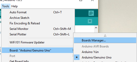
- In the Arduino IDE choose “Tools” then “Board: ‘Arduino/Genuino Uno'” then “Boards Manager” (Note: assuming this is a fresh install that’s what the Board option will be set to).
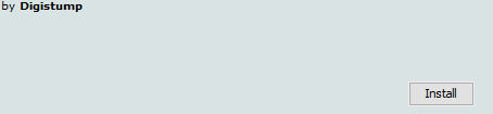
- In the Boards Manager window choose “Contributed” from the “Type” dropdown box and then choose the “Digistump AVR Boards by Digistump” option. The “Install” button will appear in the bottom right corner of this selection. Click it and wait for the install to complete.
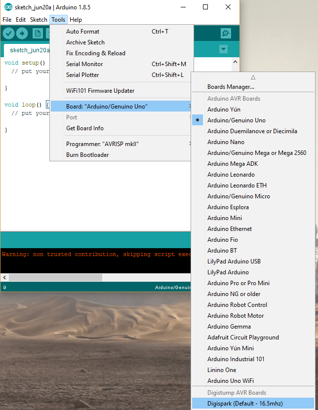
- Close the Boards Manager window. In the Arduino IDE choose “Tools” and then “Board: ‘Arduino/Genuino Uno” then “Digispark: ‘Default (16.5mhz)'”.
- You may see a note about not running the post-install script. If that’s the case, run the script manually, e.g.
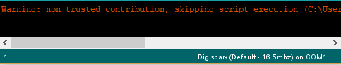
C:\Users\USERNAME\AppData\Local\Arduino15\packages\digistump\tools\micronucleus\2.0a4\post_install.bat
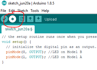
- Enter code of some sort… the below is the default 1 second blinking light example code from Digistump (assumes you have an LED attached to either I/O pin 1 or 0):
// the setup routine runs once when you press reset: void setup() { // initialize the digital pin as an output. pinMode(0, OUTPUT); //LED on Model B pinMode(1, OUTPUT); //LED on Model A } // the loop routine runs over and over again forever: void loop() { digitalWrite(0, HIGH); // turn the LED on (HIGH is the voltage level) digitalWrite(1, HIGH); delay(1000); // wait for a second digitalWrite(0, LOW); // turn the LED off by making the voltage LOW digitalWrite(1, LOW); delay(1000); // wait for a second } - Press the “Upload” button (Note: you do NOT need to have the DigiSpark plugged in at this point).
- Once the project is saved (if not already done) and compiled, you will be prompted to connect the DigiSpark (if it is not already connected):

- Watch your blinking light go!
There’s much more that can be done with these little boards, so I’ll write up more later. For right now, however, you can successfully say that you’re ready to develop with them!
The following sites were referenced in the creation of this article:
http://digistump.com/wiki/digispark/tutorials/connecting
https://github.com/digistump/DigistumpArduino/releases


Gratefuul for sharing this
LikeLike